
")

Inline pH & Flow Controlled Dosing
 A regular customer asked us to help her with a problem application of dosing a solution of waste liquid being pumped from a storage tank to a biological reactor. Depending up on the feed stock the pH of the solution would vary which would effect the bugs and hence performance of the biological reaction. The biological reaction was producing methane gas to power an engine driving a generator. The area of the dosing equipment was well outside where the reactor was located so classed as a safe area hence no Atex or Ex rating was required.
We designed and built a skid mounting unit in polypropylene with two compartments one for the control panel containing our instruments and one for the dosing pumps. The dosing enclosure was fitted with a transparent front panel to allow viewing of the dosing equipment and provide double confinement. This provided a safe and corrosion resistant housing for our equipment which was pre built and tested at our Stafford facility before shipping to the customer.
The dosing pumps where control proportionally by P7685 pH controller and the flow through the pipe by a flow meter.
So either a change in the flow or a deviation from the required pH would control the output of the dosing pumps. If the flow stopped through the system the flow controller would measure no flow and no flow would mean no dosing. If there was a deveation in the pH from the control set point which would requiring dosing pump to operate the flow signal would over ride the pH signal to dose. This would prevent dosing into pipe with no solution flow and a slug of reagent being dosed into the pipework.
As a back up a VA flow indicator with a flow switch was also fitted to act as a policeman to the flow meter.
An other feature of the system was if a small deviation existed between the pH set point and the pH measured value the doing pump would operate as controlled by the pH controller. If the flow rated doubled the dosing rate would double even if the deviation between the pH set point and the pH measured value remains the same. So the control was operated on both pH control and flow control. The traditional way of achieving this was with a complex dosing system with a dosing pump with a variable speed DC motor driving the dosing pump and a servo motor controlling the stroke length of the dosing pump with a feed back pot to tell the controller the stroke length position. This was both expensive to purchase and time consuming to install and commission (I remember I was an engineer in those days).
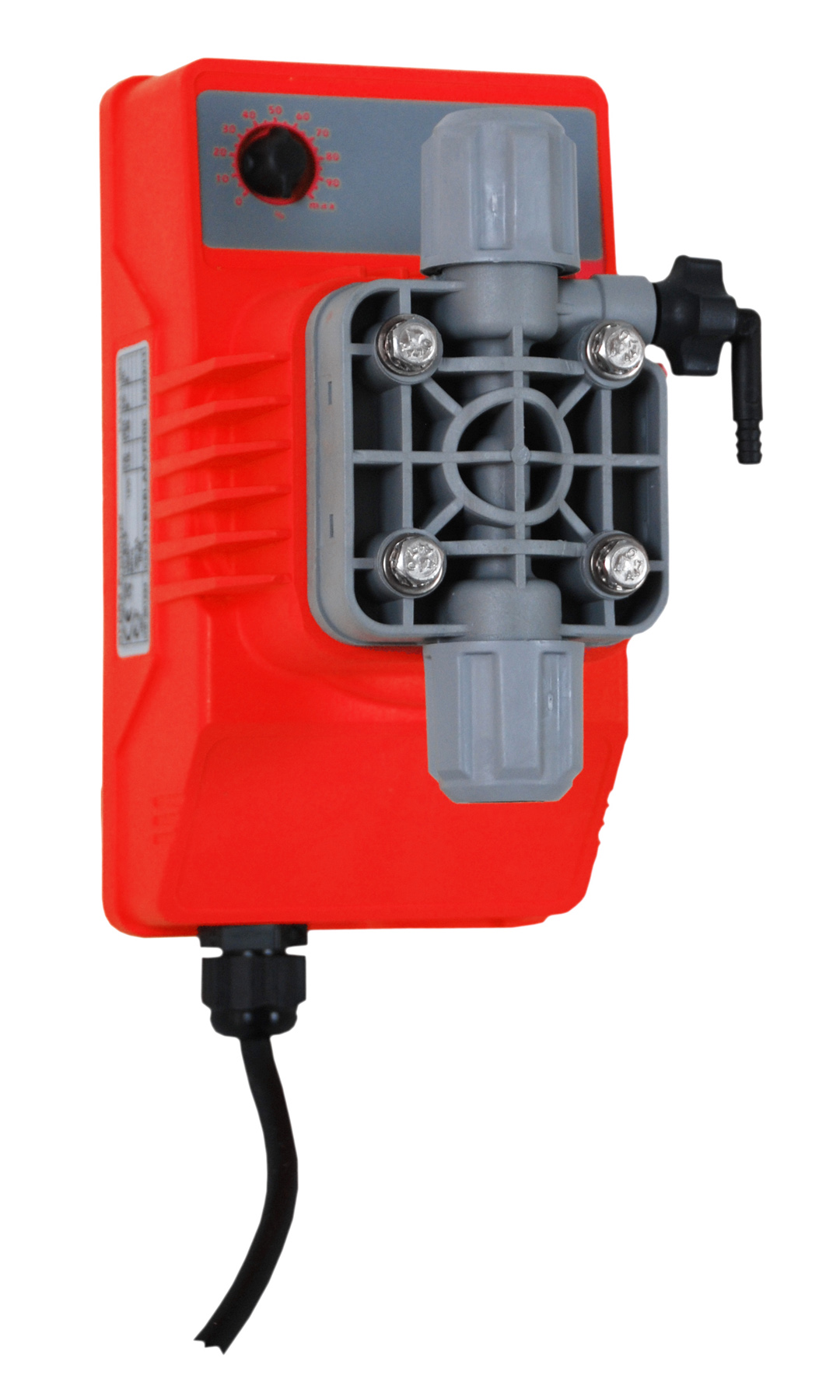
The system was fitted with a model P7685 pH controller which controlled two of our electronic dosing pumps type AT-AM which have user selectable PFM or analogue inputs to control the output of the red chemical dosing pump. The discharge to service end of the system a second P7685 pH controller measured the discharge pH and alarmed if the pH was out of specification. Both the incoming and discharge pH where measured on paperless recorder / data logger which had an ethernet card installed so the data logged information could be downloaded via the customers network on site.

Top 10 Dosing Tips
- Ensure the chemical being pumped is clean and free from foreign bodies or objects
- Always fit the foot valve/strainer assembly and injection fitting which is supplied with the pump.
- Keep the suction hose as short as possible less than 1200 mm is best
- Keep the suction hose vertical so no air locks can form.
- If pumping down hill IE the suction is higher than the discharge point or at a lower pressure such as into a pump suction (not recommended) fit an anti syphon or loading valve to prevent syphoning.
- Install the dosing hose inside a secondary hose to provide double confinement.
- Always ensure the wetted parts of the pump are comparable with the chemical reagent being dosed. Top 10 Dosing Tips if in doubt see our online chemical compatabilty chart.
- Always install duty and standby pumps where uninterrupted dosing is required
- Always keep adequate spares in stock on the site where the pump is installed.
- Fit a local electrical isolator to a dosing pump supply.
- Do not operate a pump which is leaking chemical reagent replace the seal and “O” as soon as a leak is identified.
- Always fit a dosing pump which is dosing a hazardous reagent inside a housing to provide double confinement
- Do not mount pumps above items which will be damaged by an ingress of liquids.
Sorry thats 13 dosing tips for the price of 10.
HY Pumps
We supply a lot of small dosing pumps to many different industries for dosing chemical reagents into customers process. One thing they all have in common is its essential to our customer that those pumps keep on pumping the required chemical reagents to the customers process.
We are able to supply usually from stock our remake kits part number RMK-xxxx the precise part number depends upon the pump the remake kit is required for.
Our remake kits contain all the parts to remake the wetted end of the pump which usually include the pump head with all new “O” seals, the diaphragm which is in most cases is solid PTFE construction with a mounting thread. The suction and delivery valves with the “O” seals and fitting which form the hose connection and a new set of stainless steel mounting bolts, washers and bolt caps.
For our red series electronic dosing pumps the heads are almost always PVDF being resistant to most chemical reagent being pumped. You need to specify the “O” ring material being either Viton or EPDM to suit the chemical reagent being pumped. Once you have remade the pump liquid end remember to check the mounting bolts are tight after a few hours running to prevent any leaks occurring. A good tip is to purchase a remake kit and store at close to the pump so its available if needed better still install duty and stand by pumps.